
Contrail with ASR9K and no DCGW
If you’ve reached this article, then for sure you’ve been searching for how to get Contrail (or its counterpart Tungsten Fabric) to work with a Cisco ASR9K.
One of the first links you most likely hit has been:
Contrail MX ASR903
posted in 2014 where the Cisco case is referring to IOS XE, Cisco ASR 903, which most probably, if you came here, does NOT apply to you .
One thing you have to know though, if IOS XE had a feature for building dynamic GRE tunnels, well IOS XR DOESN’T have this baked in yet. As with any vendor, based on popular demand from customers, some features get higher priority for implementing while others are left for later. This one seems to be the latter. As such, one will have to build static GRE tunnels to each Compute Node.
What is the typical Contrail/Tungsten Fabric design
A picture is worth more than a 1000 words and plus it helps those that have more of a visual memory rather than the classic word by word recalling ability.
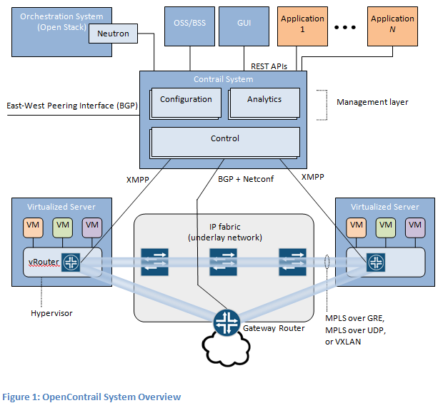
First picture is courtesy of the (http://opencontrail.org) website.
So what usually happens is this:
- You spawn a VM on a Compute Node and it gets an IP, let’s say 10.99.7.131 /32
- Then the Compute Node which has a vRouter on it announces via XMPP that it has 10.99.7.131 /32 connected behind it
- Contrail Controller which is the other end of the XMPP session receives this and then propagates the update to a DC GW router
- DCGW router has an iBGP VPNv4 with the Contrail Controller and learns:
VPNv4 Prefix 10.99.7.131 /32 NH: < IP Compute0 on Tenant Network >
MX configuration facing Contrail is done in this case not by hand but rather via the Contrail Controller Device Manager plugin (Netconf). MX configuration facing ASR9K is done by hand (inter-as Option B).
Contrail Controller sits usually on the same flat L2 networks with the Compute Nodes and the DC Gateway. In legacy setups this used to be either on Internal API or on the Storage Mgmt Network but for practical reasons (not overloading networks not meant for high traffic with data) was moved to the Tenant VLAN. As some of you might ask yourselves, yes, on the Tenant VLAN we will have both Contrail control traffic as well as data - MPLSoUDP/MPLSoGRE/VXLAN. By modifying just some values in a template one might be able to separate them but then this might bring additional complications plus issues when detecting a fault in the dataplane as it seems that keepalives happen on the control plane part.
parameter_defaults: ServiceNetMap: ContrailAnalyticsNetwork: internal_api ContrailAnalyticsDatabaseNetwork: internal_api ContrailConfigNetwork: internal_api ContrailControlNetwork: tenant ContrailDatabaseNetwork: internal_api ContrailWebuiNetwork: internal_api ContrailTsnNetwork: tenant ContrailVrouterNetwork: tenant ContrailDpdkNetwork: tenant ContrailVersion: 4
Integrated design (Cisco ASR9K = PE/ASBR and “DC GW”)
What I mean by Integrated Design:
- Contrail Computes and Controller sit in the same network with the ASR9K
- ASR9K terminates MPLSoGRE tunnels
- ASR9K does eBGP VPNv4 with Contrail Controller ( NH is preserved by the Controller despite being eBGP => NH = Compute IP for VM /32 prefixes) (in the classic case there was iBGP with the MX DC GW)
- ASR9K propagates then the information further into the MPLS backbone ( with some tweaks, see below )
- There is no need for a separate border / DC Gateway element, seamless connection into existing MPLS Net on a PE (becoming also ASBR for inter-as Option B)
Description
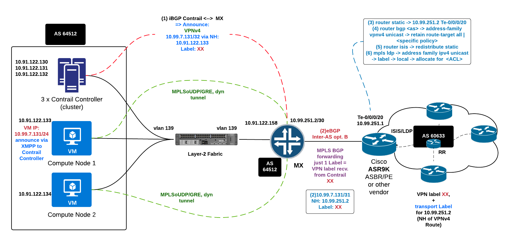
Normal Setup as described above is:
- Control Plane:
- Contrail Controller –> iBGP VPNv4 VM IP /32 via Compute IP to DC GW
- DC GW element (Juniper MX) –> eBGP inter-AS option B –> ASBR/PE Router (VM IP /32 via DC GW IP)
- ASBR/PE Router redistribute into IGP (ISIS/OSPF) the DC GW IP and assign transport label/LDP for it
- ASBR/PE Router –> MPLS Network (Backbone) –> Route Reflector
- Route Reflector –> Remote PE (termination point for the VPN/VRF = servers/other Datacenter)
- Data Plane:
- Remote servers/other datacenter -> Remote PE
- Remote PE router –> add Transport Label for NH=MX5 GW IP + VPN label for the Contrail Network (where VM IP /32 sits)
- Remote PE send label packet to P router
- P router (or chain of P routers) pop Transport Label 1 hop before ASBR/PE facing Contrail
- ASBR/PE facing Contrail forward packet with just VPN label to Compute
- Contrail Compute Node -> receive packet, strip VPN label inside the vRouter
- vRouter -> send packet to VM
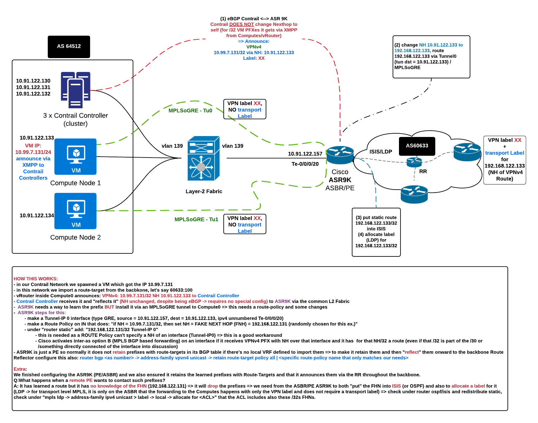
Integrated setup:
-
Control Plane:
- Contrail Controller –> eBGP VPNv4 VM IP /32 via Compute IP + inter-as Option B to ASR9K (ASBR/PE)
- ASBR/PE Router needs to force return traffic via an MPLSoGRE tunnel => Policy MAP + static Tunnel definition (ASR9K does not support dynamic tunnels YET)
- Interface Tunnel-IP0: mode gre, ipv4 src = ASR9K, ipv4 dst = Compute IP, ipv4 unnumbered
- Policy Map can’t set NH to an Interface => sets new NH = a fake NH
- Fake NH has a static route added for it over Tunnel-IP0 ( /32 ); this ensures reachability + activates MPLS BGP based forwarding (with just the VPN label present and kept)
- ASBR/PE Router –> MPLS Network (Backbone) –> Route Reflector ( VPNv4: VM IP /32 via Fake Next Hop )
- ASBR/PE Router redistribute into IGP (ISIS/OSPF) the Fake Next Hop and assign transport label/LDP for it
- Route Reflector –> Remote PE (termination point for the VPN/VRF = servers/other Datacenter)
-
Data Plane:
- Contrail Compute Node –> MPLSoGRE ( MPLSoUDP won’t work with Cisco ) terminates on –> ASR9K PE/ASBR
- ASBR/PE Router –> MPLS Net (transport + VPN label) –> P router (PHP transport label)
- P router –> PE router (VPN label) –> drop on Egress Interface (servers/other datacenter)
Return traffic coming from a distant PE and heading toward a Compute (VM /32 PFX) will have the:
- Transport Label to reach the Compute IP (router before the ASR9K will do PHP)
- VPN label
Schema
Implementation
Initial Data
Contrail Controllers: 10.91.122.130, 131, 132 Compute0: 10.91.122.133 Compute1: 10.91.122.134 ASR9K PE/ASBR: 10.91.122.157 (vlan 139 = Tenant VLAN = SUBNET 10.91.122.128/27), Interface: Te0/0/0/35.139 Fake NH for Compute0: 192.168.122.131 Fake NH for Compute1: 192.168.122.132 Tunnel Interface ASR9K -> Compute0: Tunnel-IP0 Tunnel Interface ASR9K -> Compute1: Tunnel-IP1
Inter-as Option B (general know-how)
While googling for a relevant and simple, generic image I found this one:
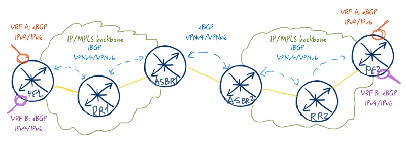
Keypoints:
- Between ASBRs there is only the VPN label
- A lot of vendor examples say that ASBR to RR should have next-hop self. While this is a nice way to do it, if you get a full BGP table in a VRF announced there, then with NH self toward the RR, all the routes will be relabelled, thus wasting up Route resources and in case of some devices needing to tweak the defaults.
- Alternative is to redistribute the nexthop (interlink between ASBRs or just the /32 IP of the remote side of the link = Nexthop) into the local IGP and also make sure LDP assigns a label for it throughout your local AS (thus ensuring there is a transport path from a remote PE to the ASBR for that NH)
Story of what was said before
In this design at the moment it is not possible to provision the ASR9K via Netconf (requires writing a plugin into Device Manager from Contrail). The ASR9K also does not support dynamic GRE tunnels (something to come in a later release perhaps) which means tunnel interfaces between ASR and Compute Nodes have to be made statically.
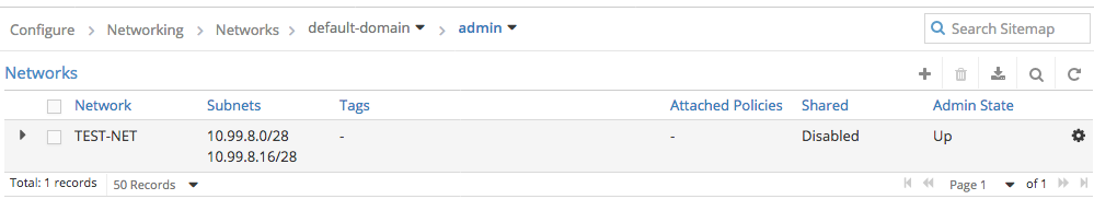
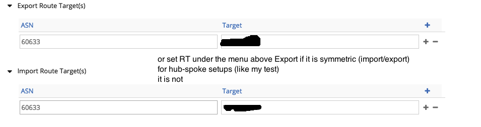
- vRouters on the Computes announce via XMPP to Contrail Controller /32 VM prefixes (with the export route targets set as per configuration)
- Contrail Controller announces them onward toward the ASR9K via eBGP VPNv4 BGP session (e.g.: 10.99.7.131 /32 via 10.91.122.133, VPN label: 24, Contrail does not change the NH that they have even if the session toward ASR9K is eBGP)
- ASR9K has static tunnel interfaces defined:
- Tunnel-IP0 : type GRE, src = ASR9K IP, dst = Compute1 IP, ipv4 unnumbered intf ASR9K facing Computes/Controller
- Tunnel-IP1 : type GRE, src = ASR9K IP, dst = Compute2 IP, ipv4 unnumbered intf ASR9K facing Computes/Controller
- ASR9K needs a workaround in order to install the return route via a tunnel interface
- first we apply a Route Policy on IN from what arrives from Contrail Controller and say: “if nexthop=Compute1 IP, then set nexthop = fake_Compute1_new_IP”
- second for MPLS BGP Forwarding to get activated and for traffic to flow through the tunnel (have the route installed), we add a static route “fake_Compute1_new_IP/32 via Tunnel-IP0 interface)
- ASR9K needs “retain route-target all | route-policy” if no VRF is defined locally that would import the route-targets for the Contrail announced networks ( if you use a “dummy” VRF or have a real VRF locally that already imports all the route-targets, then this command is not needed, albeit from a design point of view it would not look very clean)
- Traffic will flow via static tunnels (MPLSoGRE) between ASR9K and Compute Nodes
- From ASR9K into the rest of the backbone we announce the fake NH for reaching the Computes over the MPLSoGRE tunnel into ISIS and configure LDP to also allocate a transport label to them (alternative would have been to have had NH=self from ASR9K toward internal Route Reflector, then the NH = IP ASR9K facing backbone would be already in ISIS and also labelled by LDP); this is because the route is going to be announced to the RR like this (10.99.7.131 /32 via Fake Next Hop Compute0 => the other PEs need an LSP toward Fake Next Hope Compute0 in order to be able to install 10.99.7.131 /32 into FIB = CEF)
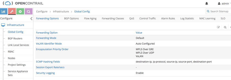
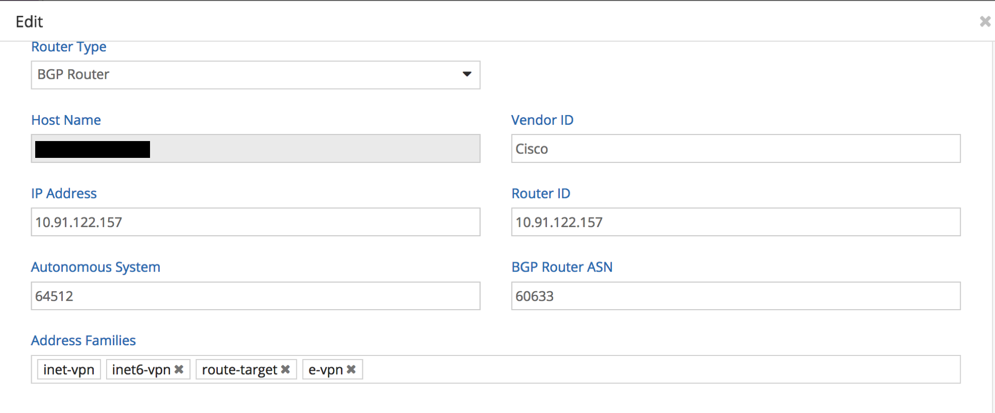
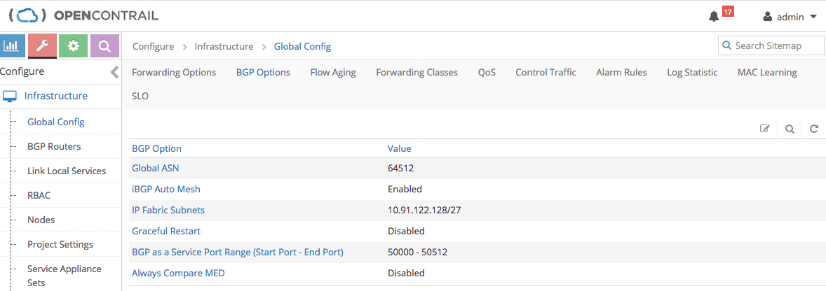
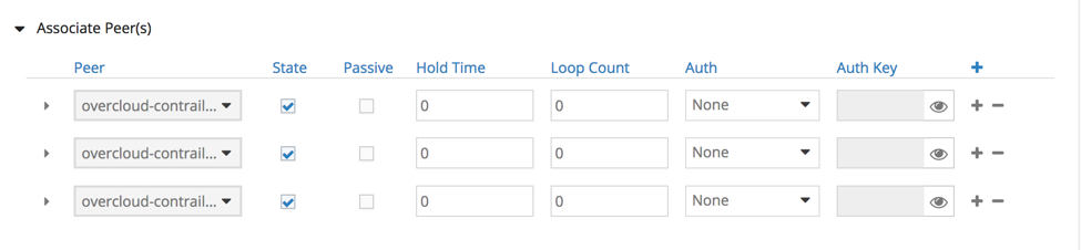
Contrail Configuration


ASR9K configuration
Static Tunnels
interface tunnel-ip0
 ipv4 unnumbered TenGigE0/0/0/35.139
 tunnel mode gre ipv4
 tunnel source 10.91.122.157
 tunnel destination 10.91.122.133

interface tunnel-ip1
 ipv4 unnumbered TenGigE0/0/0/35.139
 tunnel mode gre ipv4
 tunnel source 10.91.122.157
 tunnel destination 10.91.122.134
BGP
route-policy CONTRAIL-IN
  if next-hop in (10.91.122.133/32) then   <--- NH=Compute0, change to fake NH
    set next-hop 192.168.122.133  <--- then fake NH, static via Tun0
    done
  elseif next-hop in (10.91.122.134/32) then
    set next-hop 192.168.122.134
    done
  else
    drop
  endif
end-policy

route-policy CONTRAIL-OUT
  if extcommunity rt matches-any CONTRAIL-OUT-COMM then
    pass
  else
    drop
  endif
end-policy

neighbor 10.91.122.130 <-- same for 131 and 132
 remote-as 64512
 address-family vpnv4 unicast
  route-policy CONTRAIL-IN in
  route-policy CONTRAIL-OUT out
  retain route-target ?
  	all           Accept received updates containing at least one route target
  	route-policy  Accept received updates accepted by the specified policy
# For testing put all
# For being more specific and a bit paranoia, put a route-policy and only match the RTs
# of interest (both incoming from Contrail and imported already inside local VRFs
# defined on the ASR9K
Static Route
router static
 address-family ipv4 unicast
  192.168.122.133/32 tunnel-ip0
  192.168.122.134/32 tunnel-ip1
LDP
mpls ldp
 address-family ipv4
  label
   local
    allocate for LDP-ACL

#sh access-lists LDP-ACL
 10 permit ipv4 host 192.168.122.133 any  <-- Compute0 Fake Next Hop
 20 permit ipv4 host 192.168.122.134 any  <-- Compute1 Fake Next Hop
 30 ..... loopback of device
 ...
ISIS
router isis <MYDOMAIN-NAME>
 address-family ipv4 unicast
  metric-style wide level 2
  redistribute static
Debugging
ASR9K
ASR9K#show cef ipv4  192.168.122.133 <--Compute0 fake NH
192.168.122.133/32, version 4415 ...
 Updated ...
 local adjacency point2point
 Prefix Len 32, traffic index 0, precedence n/a, priority 4
   via tunnel-ip0, 3 dependencies, weight 0, class 0 [flags 0x8]
    path-idx 0 NHID 0x0 [0x71725b54 0x71725cf8]
    local adjacency
     local label 25311 labels imposed {ImplNull} <-- implicit Null transport label for
					 fake NH on ASBR, but programmed in CEF => OK

ASR9K#show cef vrf <LOCAL TEST VRF TO IMPORT RT EXPORTED BY CONTRAIL NET> 10.99.7.131/32
10.99.7.131/32, .... --> VM /32 IP
 Updated ...
 Prefix Len 32, traffic index 0, precedence n/a, priority 3
   via 192.168.122.133/32, 3 dependencies, recursive, bgp-ext [flags 0x6020]
    path-idx 0 NHID 0x0 [0x72b15c84 0x0]
    recursion-via-/32
    next hop VRF - 'default', table - 0xe0000000
    next hop 192.168.122.133/32 via 25311/0/21
     next hop 192.168.122.133/32 ti0          labels imposed {ImplNull 24}
# impl Null Transport label BUT VPN label = 24, fake NH installed, programmed to go
# out on Ti0 (Tunnel-IP 0) => OK
Contrail Debugging Commands
- Contrail GUI -> Interfaces -> search for IP of VM -> get TAP interface (tapxxxxx)
- vif –list | grep
=> fetch VIF number, e.g.: 0/19 - get VRF for it ( vif –get 19 ) => let’s say we obtain VRF 8
- rt –dump 8 (get route entry for your destination from VRF 8) we notice no label but NEXTHOP = 121
- nh –get 121 => find out over what INTERFACE It goes out toward this NH => shows OIF: 17
- vif –get 17 => get a TAP interface if it’s service chaining and it goes to another VM (if that other VM is layer-3 then we have to make the routing work for traffic flowing through it / or put ITS interface in the same SUBNET as the machine on the left sending traffic through it / same for the VM right, IF IT IS SERVICE CHAINING TRANSPARENT => then no changes on the config of the device needed, other that if a FW, then it has to be in Layer-2 modus)
- for packets coming from to us or service chained (label reoriginated) => mpls –get
- drops on the vRouter: dropstats on Compute Node